Overview
This page details MIRO's geometry, dimensions and conventions, which are used in translating between MIRO's signal interfaces and its physical components.
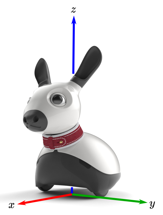
Coordinate system
MIRO uses a right-handed coordinate system, as shown in the image.
Kinematic chain
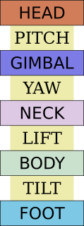
MIRO has three "kinematic" degrees-of-freedom (DOF), which are denoted LIFT, YAW and PITCH. These three DOFs connect together MIRO's four physical links (and frames of reference), denoted BODY, NECK, GIMBAL and HEAD. Together, these links and DOFs form the internal kinematic chain. BODY, in addition, is tilted with respect to the horizontal, by a fixed amount defined by the height of MIRO's rear slider; the corresponding untilted frame is denoted FOOT (footprint), and the fixed "DOF" between them is denoted TILT. Thus, MIRO's complete kinematic chain takes the form shown in the image to the left.
For conventional robotics applications, only the orientation and position of HEAD with respect to FOOT is required (FOOT usually being recovered separately by the robot navigation software). This relationship (FOOT to HEAD) can be computed from the configuration of the kinematic chain (in body_config) and the fixed parameters of the chain, in miro_platform.h.
The descriptions and values of the parameters of the kinematic chain are given in miro_platform.h. The table below summarises the parameters necessary, along with body_config, to define the FOOT-to-HEAD relationship.
| Parameter | Description |
|---|---|
| MIRO_LOC_TILT_* | Location of tilt joint in FOOT (rotational axis is y). |
| MIRO_LOC_LIFT_* | Location of lift joint in BODY (rotational axis is y). |
| MIRO_LOC_YAW_* | Location of yaw joint in NECK (rotational axis is z). |
| MIRO_LOC_PITCH_* | Location of pitch joint in GIMBAL (rotational axis is y). |
Main wheels
The descriptions and values of the parameters of the main wheels are given in miro_platform.h. The table below summarises the key parameters.
| Parameter | Description |
|---|---|
| WHEEL_DIAM_MM | Diameter of main wheels (mm). |
| WHEEL_TRACK_MM | Track of main wheels (mm). |
| MAX_SPEED_MMPERSEC | Maximum forward/backward speed (mm/sec). |
Cameras
The descriptions and values of the parameters of the cameras are given in miro_platform.h. The table below summarises the key parameters.
| Parameter | Description |
|---|---|
| MIRO_LOC_EYE_* | Location of right eye (left eye is symmetrically placed). |
| CAM_ELEVATION | Elevation of both cameras above horizontal plane. |
| CAM_DIVERGENCE | Divergence of each camera from looking "straight ahead". |
The installed position of the right-hand camera assembly is obtained as follows.
- Start with a camera assembly at the origin of HEAD facing along the +ve x-axis with upright vector along the +ve z-axis.
- Rotate assembly by
-CAM_DIVERGENCEaround z-axis to "look more right". - Rotate assembly by
-CAM_ELEVATIONaround y-axis to "look more up". - Translate optical centre to
MIRO_LOC_EYE_*.
Thus, the rotation corresponding to divergence is around an axis normal to the plane including the optical axes of both cameras, both before and after the rotation, and the upright vector of the two cameras are parallel when installed. Accordingly, a vertical line in the left camera image is vertical also in the right camera image.
Microphones
The descriptions and values of the parameters of the microphones are given in miro_platform.h. The table below summarises the key parameters.
| Parameter | Description |
|---|---|
| MIRO_LOC_EAR_* | Location of right ear (left ear is symmetrically placed). |