Overview
In case you want to add additional hardware to your MIRO robot, you can do so by using the provided Expansion Port.
Expansion Port
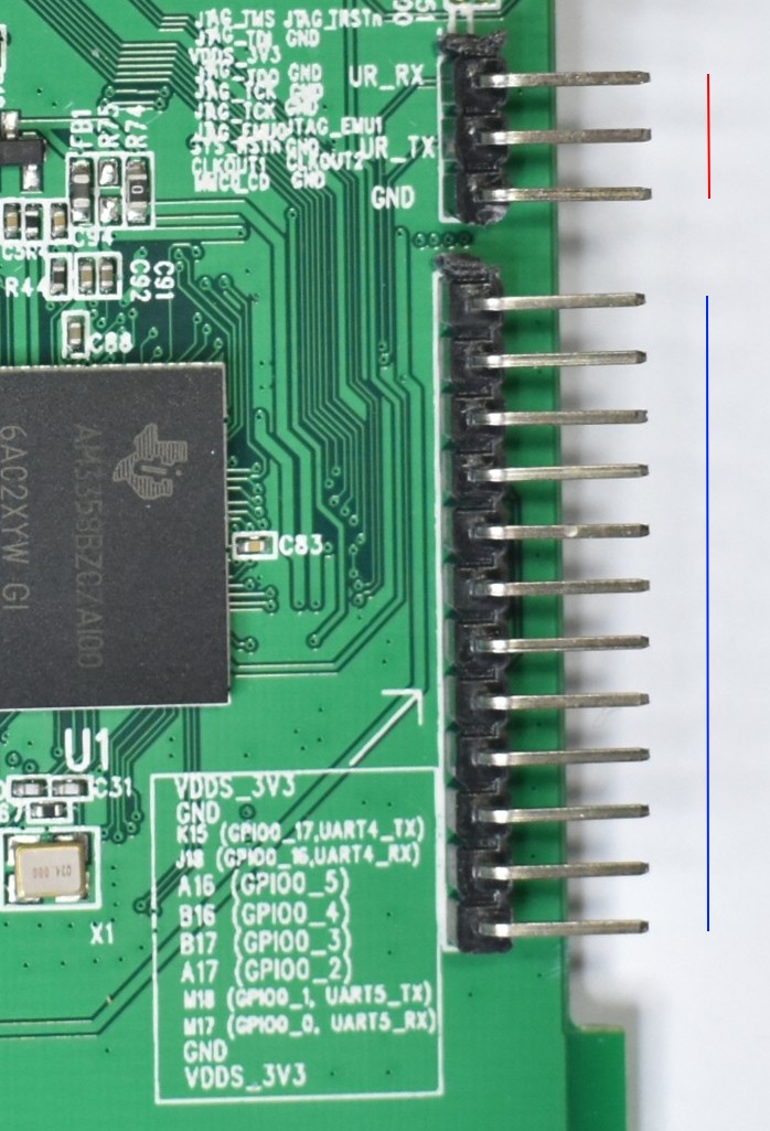
The P3 board has an Expansion Port at UC13:J10 that can be configured in various combinations. It is the 12-way connector marked in blue in the photo alongside. You can access this port from your own software running on-board P3, or provide an interface to expose it to the network allowing you to access it from off-board.
Pinout
The pinout of the port is as follows (note that the physical port is numbered 1-12 from top to bottom, which is upside-down in comparison with this table):
| Pinning for UC13:J10 | |||||
|---|---|---|---|---|---|
| pin no | pin name | AM335x ball | AM335x functions | offset | AM335x function at boot |
| 1 | VDD | 3V3 | |||
| 2 | GND | 0V | |||
| 3 | IO0 | M17 (MDIO) | uart5_rxd(2), gpio0_0(7) | 0x148 | uart5 rx |
| 4 | IO1 | M18 (MDC) | uart5_txd(2), gpio0_1(7) | 0x14C | uart5 tx |
| 5 | IO2 | A17 (SPI0_SCLK) | spi0_sclk(0), uart2_rxd(1), I2C2_SDA(2), gpio0_2(7) | 0x150 | uart2 rx |
| 6 | IO3 | B17 (SPI0_D0) | spi0_d0(0), uart2_txd(1), I2C2_SCL(2), gpio0_3(7) | 0x154 | uart2 tx |
| 7 | IO4 | B16 (SPI0_D1) | spi0_d1(0), I2C1_SDA(2), gpio0_4(7) | 0x158 | gpio0_4 |
| 8 | IO5 | A16 (SPI0_CS0) | spi0_cs0(0), I2C1_SCL(2), gpio0_5(7) | 0x15C | gpio0_5 |
| 9 | IO6 | J18 (MII1_TXD3) | uart4_rxd(3), gpio0_16(7) | 0x11C | gpio0_16 |
| 10 | IO7 | K15 (MII1_TXD2) | uart4_txd(3), gpio0_17(7) | 0x120 | gpio0_17 |
| 11 | GND | 0V | |||
| 12 | VDD | 3V3 | |||
The numbers in brackets after AM335x functions are the indices of the function into the pinmux (used below when reconfiguring the port). Thus, UC13:J10 can be configured as an SPI port and two UARTs, as three UARTs and an I2C, as eight digital I/O ports, or as some other combination of these ingredients.
Default configuration
By default, pins IO0 through IO3 are configured as two UARTs: UART5 (IO0/1) is connected to the bluetooth module, and UART2 (IO2/3) is available for use. Pins IO4 through IO7 are configured as GPIO inputs.
/dev/ttyO0.Test UART2
You can configure UART2 physically as a "loop back" by simply connecting pins IO2 and IO3 together. Data sent on IO3 will be received at IO2. Open two terminals on P3, and proceed as follows.
In the first, configure the port (disable echo and text translation, set speed) and start listening.
In the second, send some messages into the port.
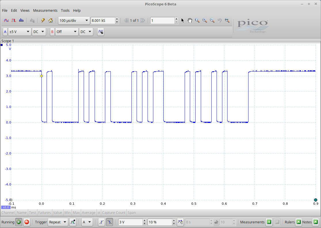
If all is well, you'll see the messages appear in the first terminal. If, meanwhile, you scope the loop back line, you'll see bursts of characters such as that shown in the image alongside for "ABC".
Test GPIO in
To listen to the four GPIO inputs, as they are initially configured, on IO4 through IO7, you can run the prepared script, as follows.
If you connect any of the pins IO4 through IO7 to a GND pin (either pin 2 or pin 11 of the Expansion Port) you will see the corresponding indicator go to "0"; during the above recording, each pin was touched in turn by a ground wire. The GPIO pins are configured, by default, with a pull-up resistor, so they read "1" when nothing is connected to them.
Test GPIO out
Any or all of IO4 through IO7 can be reconfigured as outputs easily without rebuilding the device tree. Connect together pins IO4 and IO5, and run the prepared script, as follows.
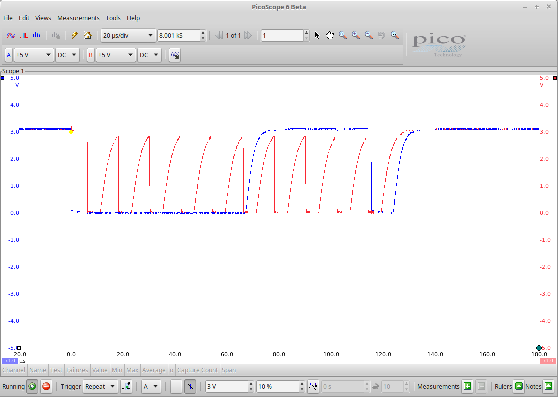
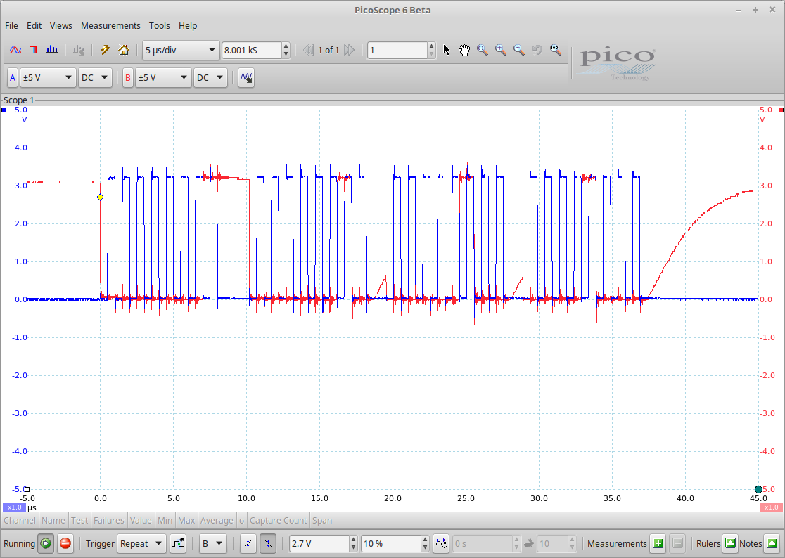
The script configures IO4 as an output, and listens to IO5 through IO7. Since IO4 is connected to IO5, you can see the state toggling on each cycle.
Reconfiguring Expansion Port
The Expansion Port is configured through the Linux Device Tree mechanism.
/usr/share/miro/event/system_ready.sh that runs start_daemon.sh.Review pin configuration
Since device tree operation is somewhat opaque, you may wish to follow the effect that your configuration changes have on the physical device. Proceed as follows to review the pin control registers for pins IO0 through IO7.
The above command queries the state of the pinmux interface of the AM3358 control module. See Chapter 9 of the device Technical Manual (the register addresses are listed in table 9-10) and Chapter 2 of the device datasheet (Table 2-7 lists the eight multiplexed functions available on each physical pin). The above is the default configuration for P3.
For instance, pin IO0 is at offset 0x148 (from base address 0x44E10800), which TM 9-10 indicates is for pin mdio; pin mdio appears in DS 2-7 at ZCZ ball number M17; function 2 of that pin is uart5_rxd. Therefore, the pin control register at offset 0x148 needs to have muxed function 2 selected. Table 9-60 indicates how to read the register value: "0x32" reads back as "receiver enabled, pullup selected, pullup/pulldown enabled, mux function 2", which amounts to a GPIO input pin.
/sys somewhere (see the documentation for the particular peripheral interface for details).Rebuild device tree
The device tree is stored in binary form on the SD card in /boot.
To modify it, you will decompile the device tree binary (.dtb) to a device tree source (.dts) file, make your changes, and then recompile back to binary, before installing the resulting file back to /boot. The device tree compiler dtc is available on-board, but it does not interact with the system so you may find it easier to use your workstation to make modifications. Either way, the procedure is as follows.
Decompile binary
To decompile the .dtb to a .dts, use a command of this form.
Modify source file
The source file is plain text—modify it in any text editor.
Recompile binary
To recompile the modified .dts to a .dtb, use a command of this form.
Install new binary
Copy the new .dtb to /boot on the SD card, and reboot MIRO to effect the changes.
.dtb file to /mnt/rootfs/boot/am335x-miro.dtb from the copy in the MDK at ~/mdk/extern/yocto/am335x-miro.dtb.Modify device tree
Below are a few examples for modifying your device tree.
UART4
Before we can enable UART4, we first need to disable GPIO pins gpio0_16 and gpio0_17, which share physical pins IO6/7. To do this, search in the .dts for the token expansion_port_pins. Within that section, find the field pinctrl-single,pins, which by default reads <0x158 0x37 0x15c 0x37 0x11c 0x37 0x120 0x37>. Each enabled GPIO pin is represented by a pair in this field, and the first value in each pair is the offset value from the table at the top of this page. Delete the last four entries in this field to deconfigure gpio0_16 and gpio0_17.
To enable UART4, we first have to configure the pinmux. Find the token pinmux_uart5_pins in the .dts, and copy it to a section just above. Rename the section to pinmux_uart4_pins: pinmux_uart4_pins, delete the two lines containing the token phandle, and change the pinctrl-single,pins field to read <0x11c 0x33 0x120 0x3>. Note that we have based the value for this field on that used for UART5, with the offsets changes to 0x11c and 0x120 (see table) and the pinmux fields both changed to 3, the mux index (see table).
Next we have to enable the peripheral UART4; internally, this is known as uart5 (ti,hwmods = "uart5"), which you'll find listed under the token serial@481a8000. Simply change the status field to read okay rather than disabled, and add a reference to the pinmux section at the bottom (two lines starting pinctrl) so that the pinmux gets actioned.
Recompile and install the device tree to /boot, then reboot your MIRO. When it starts up again, confirm the new pinmux configuration:
Note that the last two pins have changed from pinmux 7 to pinmux 3, reflecting their switch over to the UART peripheral.
To test the new UART port, connect a loop back cable between pins IO6 and IO7, and then run the transmitter and receiver in two separate P3 login terminals, as follows.
More or less GPIO
You can disable all the UARTs and just have eight GPIO pins. Update the field pinctrl-single,pins under expansion_port_pins to read <0x148 0x37 0x14C 0x37 0x150 0x37 0x154 0x37 0x158 0x37 0x15c 0x37 0x11c 0x37 0x120 0x37>. Disable UART2 and UART5, which are known internally as "uart3" and "uart6"; set the field status to read disabled under sections serial@48024000 and serial@481aa000. Reboot, and see the scripts test_gpio_*.sh to get started.
To have less GPIO, you can remove entries from the pinctrl-single,pins field. To have none at all, however, you can simply find the section expansion_port_pins_helper and set status to disabled; this frees all GPIO pins for other uses.
I2C
I2C1 is section i2c@4802a000 and I2C2 is section i2c@4819c000. To enable the former, first remove the entries 0x158 0x37 0x15c 0x37 from pinctrl-single,pins of expansion_port_pins to release the pins from use by the GPIO module, then change status under i2c@4802a000 to okay. Rebuild, reboot, and IO4/5 are now configured as I2C1, the interface for which will appear at /dev/i2c-1.
We can test this interface by running the detection program i2cdetect.
clock-frequency (for example, use clock-frequency = <0x61a80> for 400kHz).
i2c@4802a000 is known internally as "i2c2", and i2c@4819c000 as "i2c3"; try to ignore this, these refer to physical devices I2C1 and I2C2, respectively. I2C0 (aka "i2c1") is used on-board UC13 and its configuration should not be changed.SPI
To use the SPI port, find spi@48030000 and set the field status to okay; find serial@48024000 (UART2) and set status to disabled. After installing the .dtb and rebooting, you'll see a pin configuration like this:
If you followed the instructions above exactly, you'll see that SPI is now configured on IO2-IO5, but that IO6 and IO7 are not configured as GPIO anymore. That's because the device tree is still requesting pins IO4 through IO7 for GPIO, and IO4 and IO5 are not available (they are configured as SPI). To reinstate the GPIO function on IO6 and IO7, you need to remove the IO4 and IO5 configuration from expansion_port_pins, as above (remove the first four entries of eight from pinctrl-single,pins).
You will now find a device at /dev/spidev*. Learn more about that device here. You can test the SPI interface as follows.
Daemon
One possible way to use the Expansion Port would be to write a daemon to run on P3 that exposes the port to the network, publishing its state on a ROS node and/or receiving signals through the ROS interface to push onto the port. More generally, you could incorporate use of the GPIO port into the wider control system of your robot or robots. Of course, you can exchange data to or from any of the available peripherals in a similar way.
A very simple port reading daemon is supplied; try it out as follows. Pin IO4 should be configured as a GPIO input (the default configuration for this pin).
First, on your workstation, run roscore. Next, on MIRO, enable and test the GPIO input pin.
Thirdly and finally, compile and start the daemon on MIRO:
Now you can run rostopic echo /miro_robot_daemon_test on your workstation to observe the outgoing signal. If you touch a wire between pin IO4 and GND (available on pin 2 or pin 11 of the Expansion Port), you'll see the signal change at your workstation (pin IO4 is configured with a pull-up resistor, so connecting it to ground will change its level).