MIRO Assembly Guide
Parts
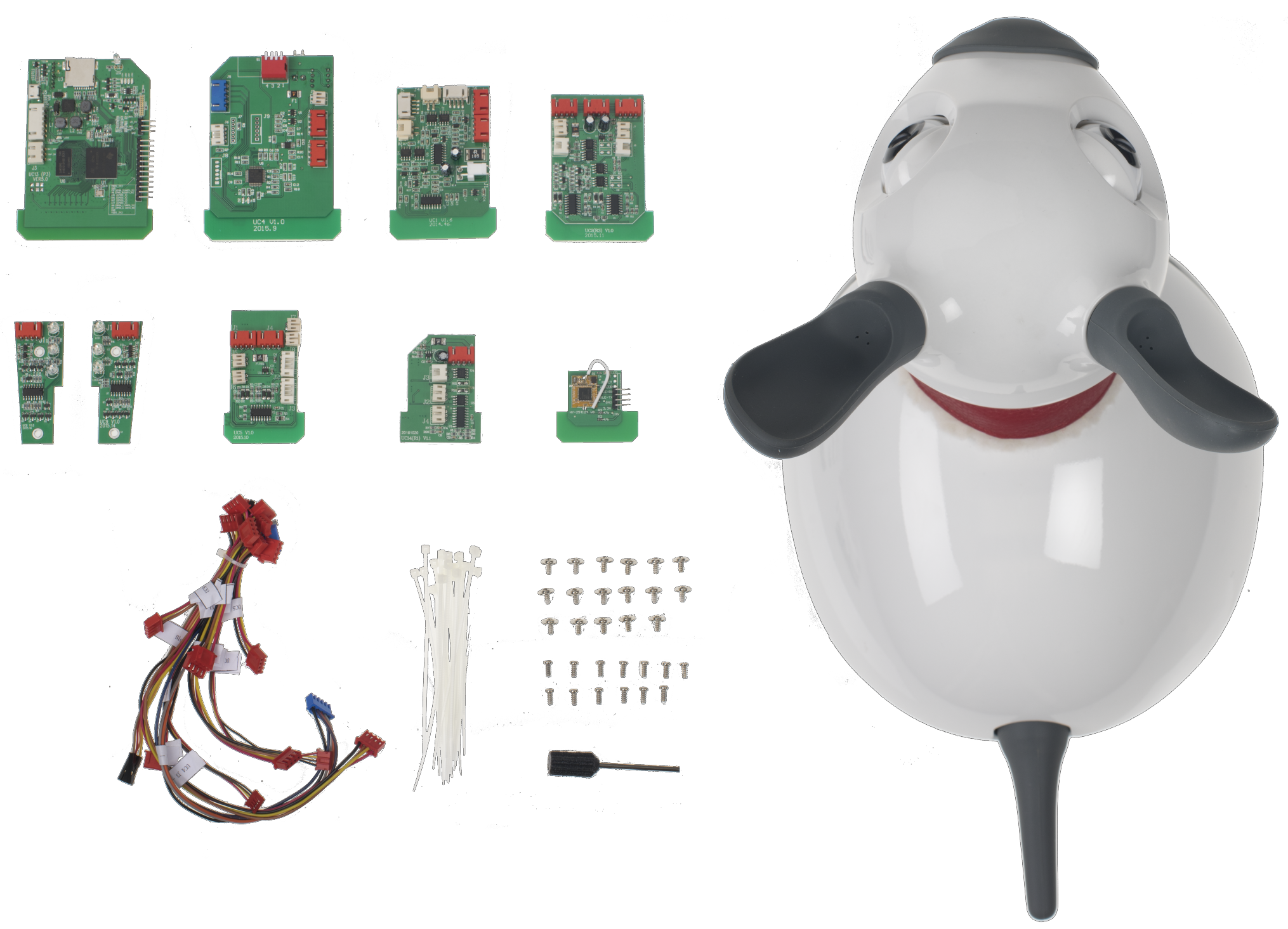
Check that all parts have been correctly supplied—these are shown in the diagram, right, and summarized in the table below.
| Part | Quantity |
|---|---|
| MIRO (Body & Head) | 1 |
| Board UC1 | 1 |
| Board UC2 | 1 |
| Board UC4 | 1 |
| Board UC5 | 1 |
| Board UC13 | 1 |
| Board UC14 | 1 |
| Bluetooth Module | 1 |
| Cable UC1:J2 - C1:J8 4-pin | 1 |
| Cable UC2:J5 - P1:J4 4-pin | 1 |
| Cable P1:J5 - C1:J2 4-pin (blue plugs) | 1 |
| Cable P1:J3 - C1:J3 4-pin | 1 |
| Cable UC5:J1 - UC2:J4 4-pin | 1 |
| Cable UC6:J1 - UC1:J3 4-pin can be found attached inside the body shell | 1 |
| Cable UC8:J1 - UC2:J1 4-pin | 1 |
| Cable UC9:J1 - C1:J7 4-pin | 1 |
| Cable UC14:J1 - UC5:J4 4-pin | 1 |
| Cable Bluetooth (BLE-J1 to P3) 4-pin female-female | 1 |
| Bag of Screws | Plenty |
| MIRO head-opening tool | 1 |
| Cable Ties | Plenty |
| Spare Sliders | 2 |
Tools
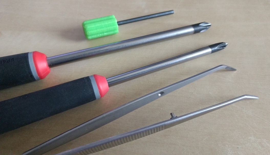
You will need Philips size 1 and size 2 (PH1 and PH2) screwdrivers, and a pair of good tweezers is advised.
MIRO's head is already assembled on delivery, so several of the control boards are already installed. You will not usually need to open the Head shell; if you do (to service a part, for example) you will need the MIRO head-opening tool, which is supplied with MIRO and shown in the diagram.
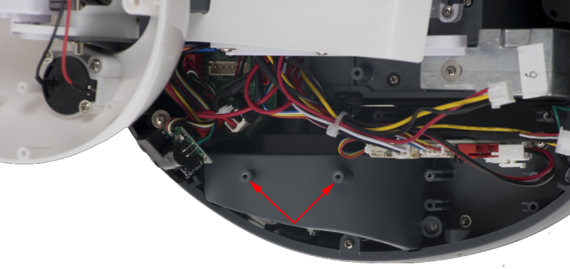
Remove Body Shell

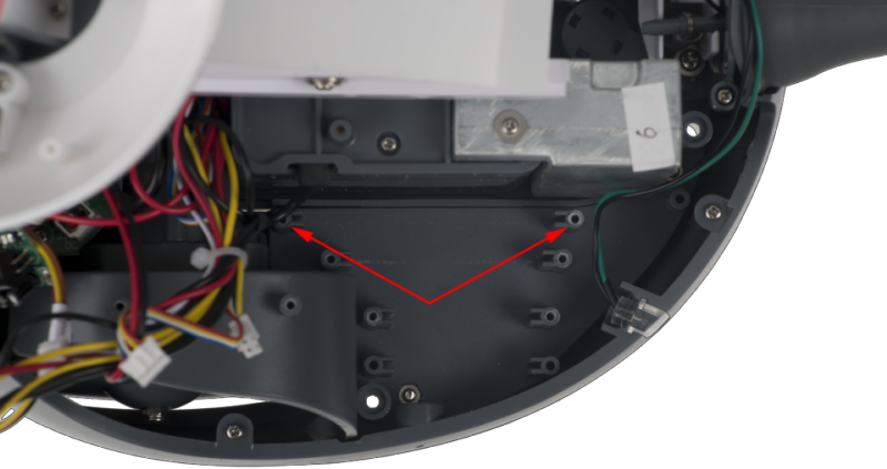
First, invert MIRO, and use the PH2 screwdriver to remove the 6 screws from the underside that secure the body shell in place (see image). Turn MIRO back over. MIRO ships with the neck lift actuator disconnected (you will find the screw for this in a bag taped to the neck), so you will be able to push the head forward and down far enough so that the body shell is freed.
Gently lift and slide the shell to the rear of MIRO to remove, taking care to disengage the plastic slot guard from its home in the slot under MIRO's body shell. Store these, and all screws, safely, for reassembly.

The additional image, left, shows one way to safely invert your MIRO.
Install boards
Most of the remainder of these instructions detail installation of the circuit boards that populate MIRO's body cavity. Each board is labelled on its upper side in white paint with its code, usually at the bottom edge of the board—these codes all start with UC. Installation of each board is covered in a section, below.
Some of the connectors on each board must be plugged in to other parts of MIRO using the cables provided. The connectors on each board are labelled, for example as J1, in white paint on the upper side of the board. The table in each section below indicates how to connect each end of each cable, by referencing these connector names. You will also find the same connection instructions on a label attached to each cable.
C1
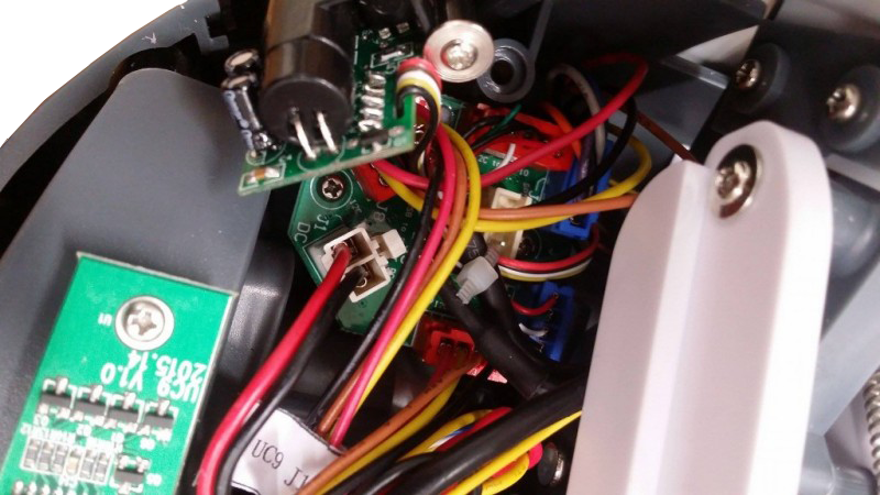
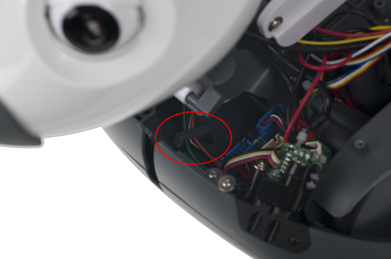
The C1 board is the the connection point between the body and the head, and comes pre-installed. It just needs the battery power connector attaching (see image).
Connections
| Connector | Cable | Destination | Notes |
|---|---|---|---|
| J1 | 2-pin | Battery Box | Black & Red cable |
UC13 (P3)

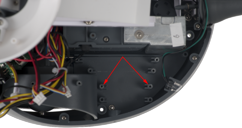
UC13 is the P3 "forebrain" processor board. Secure the board in place (see image) with 2 × flanged screws.
Do not, at this stage, install the provided SD card—this will be installed in a later step, below.
Connections
| Connector | Cable | Destination | Notes |
|---|---|---|---|
| UC13:J3 | 3-pin | Battery box | Black, yellow & red cable |
| UC13:J4 | 6-pin | Neck loom | J4 (unlabelled) found between between J3 & J5 |
| Wi-Fi chip | Antenna | Tail | Take the end of the antenna (protruding from inside the tail) and connect it to the Wi-Fi chip that is attached to the back of UC13. |
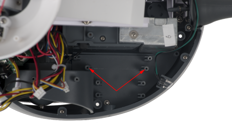
UC1
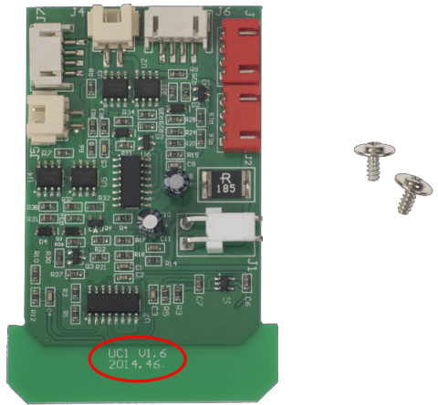
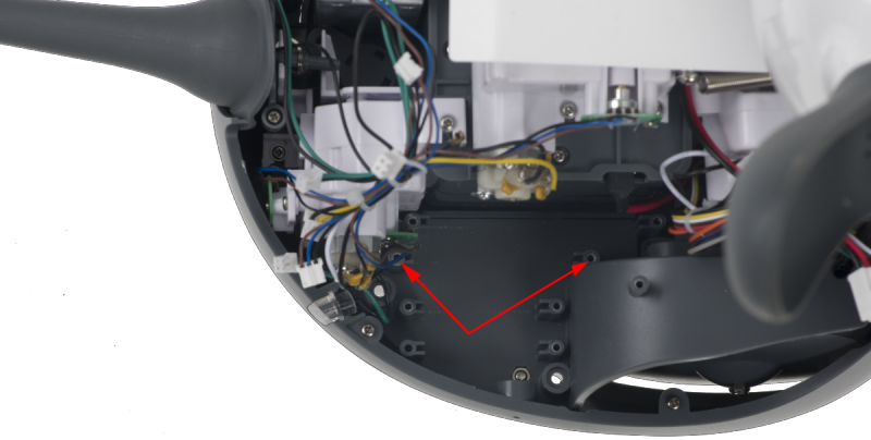
UC1 is the driver board for MIRO's wheel motors. Secure UC1 to the body using 2 × flanged screws (see image).
Connections
| Connector | Cable | Destination | Notes |
|---|---|---|---|
| UC1:J4 | 2-pin | Right wheel motor | Black & white cable |
| UC1:J6 | 4-pin | Right wheel motor optical encoder | Destination found underneath motor. Blue, white, yellow & red cable. |
| UC1:J5 | 2-pin | Left wheel motor | Black & yellow cable |
| UC1:J7 | 4-pin | Left wheel motor optical encoder | Destination found underneath motor. Blue, white, yellow & red cable. |
| UC1:J1 | 2-pin | Battery Box | Black & red cable |
| UC1:J2 | 4-pin | C1:J8 | Use provided cable |
| UC1:J3 | 4-pin | UC6:J1 | UC6 found in body shell. Do not complete this step yet, see Finalising. |
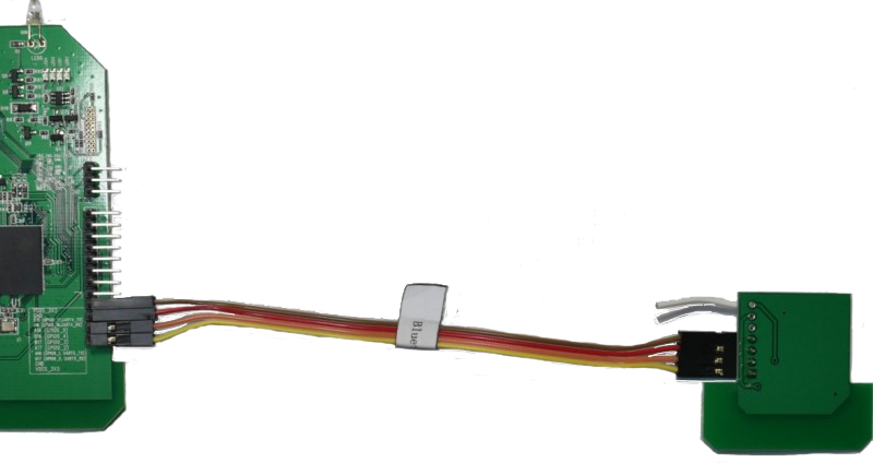
Bluetooth module
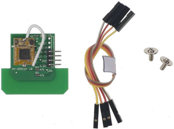
Secure the board in place (see image) with 2 × flanged screws. Once installed, straighten the antenna as shown in the picture.

Connections
| Connector | Cable | Destination | Notes |
|---|---|---|---|
| BLE-J1 | Female-Female labelled cable | UC13 (P3) | Connect the pins to the bottom 4 pins on UC13 (P3), in the order shown above. |
UC4 (P1)
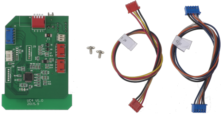
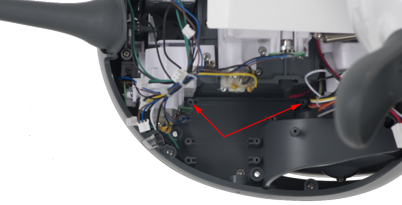
UC4 is the P1 "spinal" processor board. Secure it in place with 2 × flanged screws.
Connections
| Connector | Cable | Destination | Notes |
|---|---|---|---|
| UC4:J5 | 5-pin | C1:J2 | Use provided blue-capped cable; secure under fasteners under neck (see image) |
| UC4:J3 | 4-pin | C1:J3 | Use provided cable; secure under fasteners under neck (see image) |
| UC4:J2 | 2-pin | Speaker | Black & Orange Cable; speaker at front left under C1 |
| UC4:J1 | 2-Pin | Battery Box | Black & red cable, connection is on rear of UC4 |
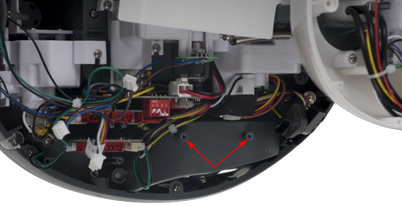
UC2

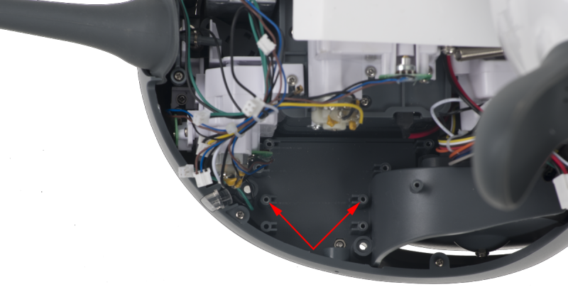
UC2 is the driver board for the neck lift & yaw motors. Secure UC2 in place (see image) with 2 × flanged screws.
Connections
| Connector | Cable | Destination | Notes |
|---|---|---|---|
| UC2:J5 | 4-pin | UC4:J4 | Use provided cable |
| UC2:J7 | 3-pin | Neck yaw gearbox motor encoder | Brown, white & yellow cable (or brown, blue & black on later models) |
| UC2:J6 | 2-pin | Neck yaw gearbox motor | Black & white cable |
| UC2:J2 | 3-pin | Neck lift gearbox motor encoder | Black, blue & brown cable |
| UC2:J3 | 2-pin | Neck lift gearbox motor | Yellow & black cable |
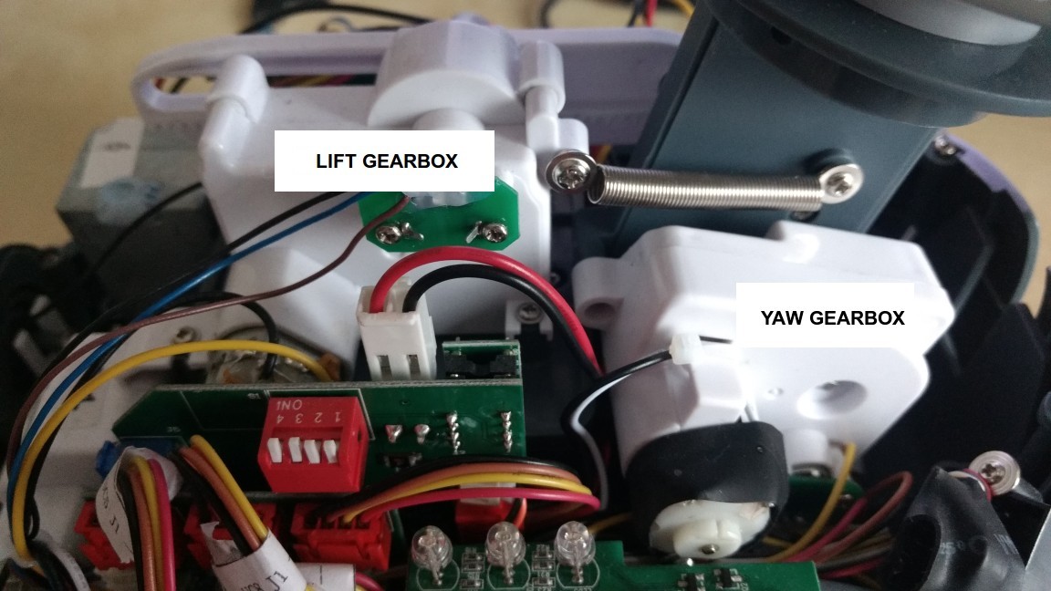
The image below identifies the two gearboxes, lift and yaw. Each has an associated two-way cable from the motor, and three-way cable from the sensor.
UC5
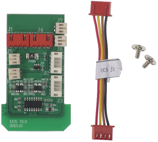
UC5 is the front sensor array board. The board is secured in place (see image) with 2 × flanged screws.
Connections
| Connector | Cable | Destination | Notes |
|---|---|---|---|
| UC5:J1 | 4-pin | UC2:J4 | Use provided cable |
| UC5:J6 | 2-pin | Rear light sensor (right) | Very short green & black cable |
| UC5:J5 | 2-pin | Rear light sensor (left) | Long green & black cable |
| UC5:J2 | 5-pin | Cliff sensor (front left) | Red, brown, white, yellow & black cable |
| UC5:J7 | 2-pin | Front light sensor (left) | Green & black, found underneath cliff sensor |
| UC5:J3 | 5-pin | Cliff sensor (front right) | Red, brown, white, yellow & black cable |
| UC5:J8 | 2-pin | Front light sensor (right) | Yellow & black, found underneath cliff sensor |
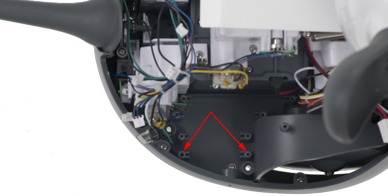
UC14
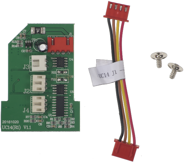
UC14 is the tail motor control board. Secure the board in place (see image) with 2 × flanged screws.
Connections
| Connector | Cable | Destination | Notes |
|---|---|---|---|
| UC14:J1 | 4-pin | UC5:J4 | Provided cable |
| UC14:J3 | 2-pin | Tail gearbox motor | Black & white cable |
| UC14:J2 | 3-pin | Tail left/right potentiometer | Black, blue & brown cable found at the back next to the tail On models with serial number 0051 and later, this cable is yellow, white & black. |
| UC14:J4 | 3-pin | Tail up/down potentiometer | Black, blue & brown cable found on the side of the tail motor gearbox On models with serial number 0051 and later, this cable is red, white & black. |
UC8
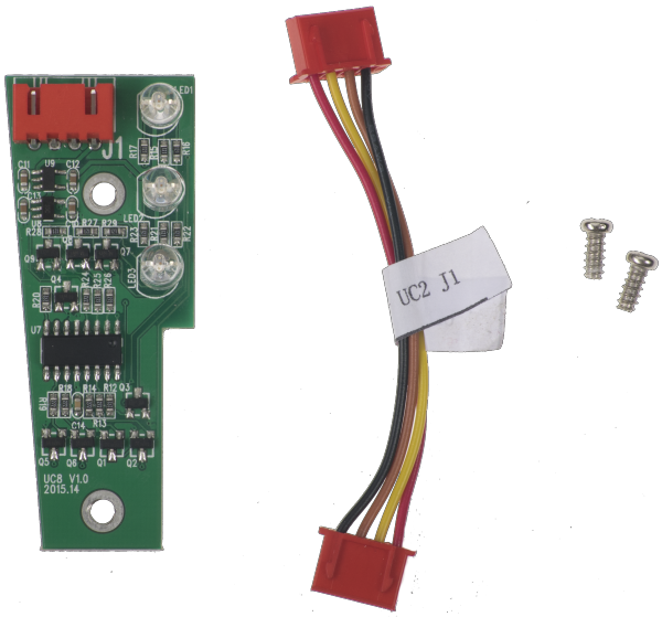
UC8 is the LED control board (right). This part comes pre-installed.
Connections
| Connector | Cable | Destination | Notes |
|---|---|---|---|
| UC8:J1 | 4-pin | UC2:J1 | Use provided cable |
UC9
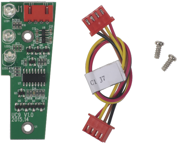
UC9 is the LED control board (left). This part comes pre-installed.
Connections
| Connector | Cable | Destination | Notes |
|---|---|---|---|
| UC9:J1 | 4-pin | C1:J7 | Use provided cable |
Calibration
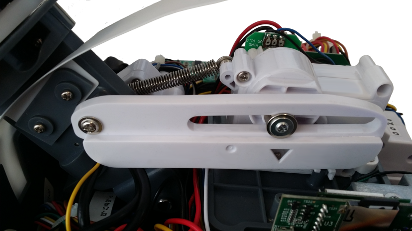
The next step requires MIRO to be powered up, so you should install fresh Batteries next. Select mode 8[1], "calibrate" (click here to find out how), and then turn MIRO on. The LIFT axis (the rack and pinion drive system that lifts MIRO's neck up and back) will move to its calibrate position.
Leave MIRO powered up whilst you attach the rack & pinion with the arrow cut-out aligned with the shaft, as shown in the image. Use the flanged bush to mount the back end of the rack and secure it with the self-tapping screw (both parts are in a plastic bag taped inside MIRO's body shell on arrival).
[1] Mode 8 is represented in binary form on the DIP switches as 1-0-0-0.
Test operation
Select mode 12[2], demo mode (click here to find out how), and switch MIRO on. If all is well, MIRO will start running in demonstrator mode. You can take a look at the Wrangling page for some insight into what is happening—briefly, MIRO should move around and respond to movement and loud sounds, and should vocalise and light up.
If demo mode seems to be operating more-or-less as expected, most things are probably connected up correctly. If not, and especially if your robot sounds like a telephone, go over all the connections you have made and check them carefully to ensure they are fully home. If necessary, look at the Testing page to see if you can identify any problems.
[2] Mode 12 is represented in binary form on the DIP switches as 1-1-0-0.
Install SD Card
Before proceeding, make sure MIRO is turned off underneath.
Install the SD card by inserting it in the slot as shown below (magenta highlight).
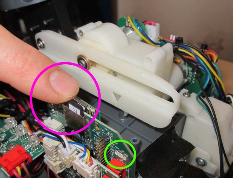
After a few seconds, the blue light will go out. If it does not, remove the SD card and try again. If this still does not work, remove MIRO's batteries, install the SD card cleanly, make sure MIRO is turned off, and finally replace the batteries.
Turning on
You are now ready to turn MIRO on for the first time: please follow the instructions at Boot And Shutdown.