Overview
This page provides protocols for testing your robot if something seems to be wrong. Generally, troubleshooting robot operation will consist of identifying which item has failed, and checking the connections to it or, if required, changing it out. To this end, the following table is key.
Component and board associations
There follows a list of the installed boards along with their function; if a particular function is missing, suspect that the associated board not properly connected or even has failed.
| Board | Function |
|---|---|
| UC1 | Wheel motors |
| UC2 | Neck lift (rack & pinion) and yaw (side-to-side) |
| UC4 | Spinal processor |
| UC5 | Cliff & light sensors |
| UC6 | Body touch sensors |
| UC7 | Brainstem processor |
| UC8 | LED display left |
| UC9 | LED display right |
| UC10 | Head pitch (up and down) |
| UC11 | Head touch sensors |
| UC12 | Sonar ranger |
| UC13 | Forebrain processor |
| UC14 | Tail motors |
| UC15 | Ear motors |
| UC18 | Eyelid motors |
If a board has worked once before, then board failure is very unlikely, so always suspect a loose connection first. Once you have isolated the failing board, unplug and replug all of its connections (not just the ones you are suspicious of) and give each a close visual inspection whilst it is apart. Reconnect everything and see if the problem is cleared. If not, board failure is a possibility—get in touch to discuss how to proceed.
Testing modes
One way to test your robot is to place it in demo mode, which works out most of the sensors and actuators. See Wrangling for an overview of how it should behave. You can also try Workout mode.
Python GUI
A more direct, and targeted, way to test individual components is to connect to the Python GUI Client. If you are a developer, this will be relatively straightforward since it is part of the "getting to know MIRO" experience to learn how to use this GUI. In this GUI, it will be very clear if an individual component is not working.
I2C bus fault
If your MIRO starts to sound like a telephone, there is a fault on the I2C bus. I2C bus faults can usually be isolated and fixed by the user. This section will walk you through the process.
MIRO's I2C bus is how the main processing stack (in this case, P1) communicates with all the peripheral boards that manage MIRO's actuators and sensors. Physically, it is easily recognised by the red connectors and 4-way cables present on most of MIRO's boards (the cable colours are red, yellow, brown and black). If any device on the bus causes a fault, the whole bus cannot operate, and the warbling warning sound is generated whenever MIRO is turned on.
The sub-sections below cover each possible cause of an I2C bus fault, in order of likelihood and ease of diagnosis. You should follow through each section in order until you find the fault.
First thoughts
First, consider whether MIRO might have been damaged. Could a cable have been tugged? Was MIRO dropped or knocked?
If so, check MIRO over for physical damage, focusing particularly on the red connectors and 4-way cables of the I2C bus. The I2C cables are all equivalent, so if you suspect one of them is damaged you can try swapping it for another.
Whether or not you have reason to suspect acute damage, you can check all I2C connectors visually, and give them a wiggle to see that they are soundly connected. There are connectors inside the head as well as inside the body, but check in the body first because the access is easier.
You can run these wiggle checks whilst the alarm is sounding—an attempt is made to reset the bus once per second, so the alarm will silence if you find and fix the fault.
UC6 shield inadequate
To begin a more formal diagnostic, start by removing the body shell.
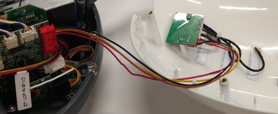
There is one small peripheral board mounted up inside the body shell—this is UC6. It connects to the rear edge of UC1, on the left side of the body, through one of the I2C cables with red 4-way connectors at either end. Since this is the easiest place to start checking, we start here.
Some early MIROs shipped with insufficient shielding on the underside of UC6 (see image, right, for a view of a correctly-installed shield). If your warning warble stops as soon as you remove MIRO's body shell, you are probably facing this issue. Contact technical support to receive a replacement part and guidance on fitting. You may also be able to see physical damage to the shielding under UC6 caused by metal parts piercing the installed shield (see image, right).
Whether or not this fault is present, disconnect UC6 now.
General diagnostic
MIRO's I2C bus has physical "tree topology". Each board is connected to a parent board, and some boards branch the bus to more than one daughter. Thus, disconnecting any I2C cable eliminates some section of the bus (perhaps as little as a single peripheral board). If the faulty part is disconnected from the bus, the fault will clear and the warning sound will stop.
The general approach to finding a fault, then, is to disconnect sections of the bus until the fault clears, then add components back until the fault is reintroduced. At the end of this process, either a cable or a board will have been identified that is faulty. Technical support can then ship a replacement part and provide guidance, if required, on its installation. Disconnect either end of an I2C cable to remove some components from the bus.
This section will guide you through doing this in one way, but you can isolate parts of the bus in any order and achieve the same effect. If you suspect a particular board or area of MIRO, go ahead and start your search there.
First, you should shutdown your MIRO, and remove the SD card. After doing this, you can turn MIRO on and off as quickly as you need to, and will not have to keep listening to the warning siren. Once the diagnostic is finished, turn MIRO off underneath, replace the card, and the power lights will extinguish after a few seconds.
Right or Left?
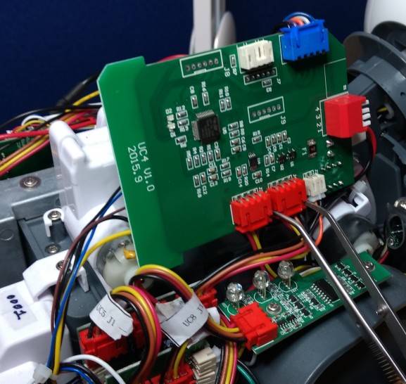
All the peripherals on MIRO's right hand side are connected to the bus by the cable from UC2:J5 to UC4:J4. This is the cable the tweezers are attached to in the image, right. You can disconnect it at the out-board end without pulling out UC4, as shown. If disconnecting this cable clears the fault, you do not need to pull out the board UC4.
Otherwise, unscrew two screws securing UC4, and pull it out as shown in the image. You can now disconnect both cables on UC4. UC4:J4 links in the right hand side of MIRO; UC4:J3 links in everything else (by connecting under MIRO's neck to the small distribution board, C1, at connector C1:J3).
If you have pulled out both cables from UC4, and the fault is not yet cleared, then board UC4 itself is at fault. If the fault clears when you unplug UC4:J4 (marked by the tweezers in the image), the fault is on the right hand side of MIRO, and you can continue unplugging items to zero in. If the fault clears when you unplug UC4:J3, the fault is on MIRO's left hand side, or in the head, and you should continue below.
Head or Body?
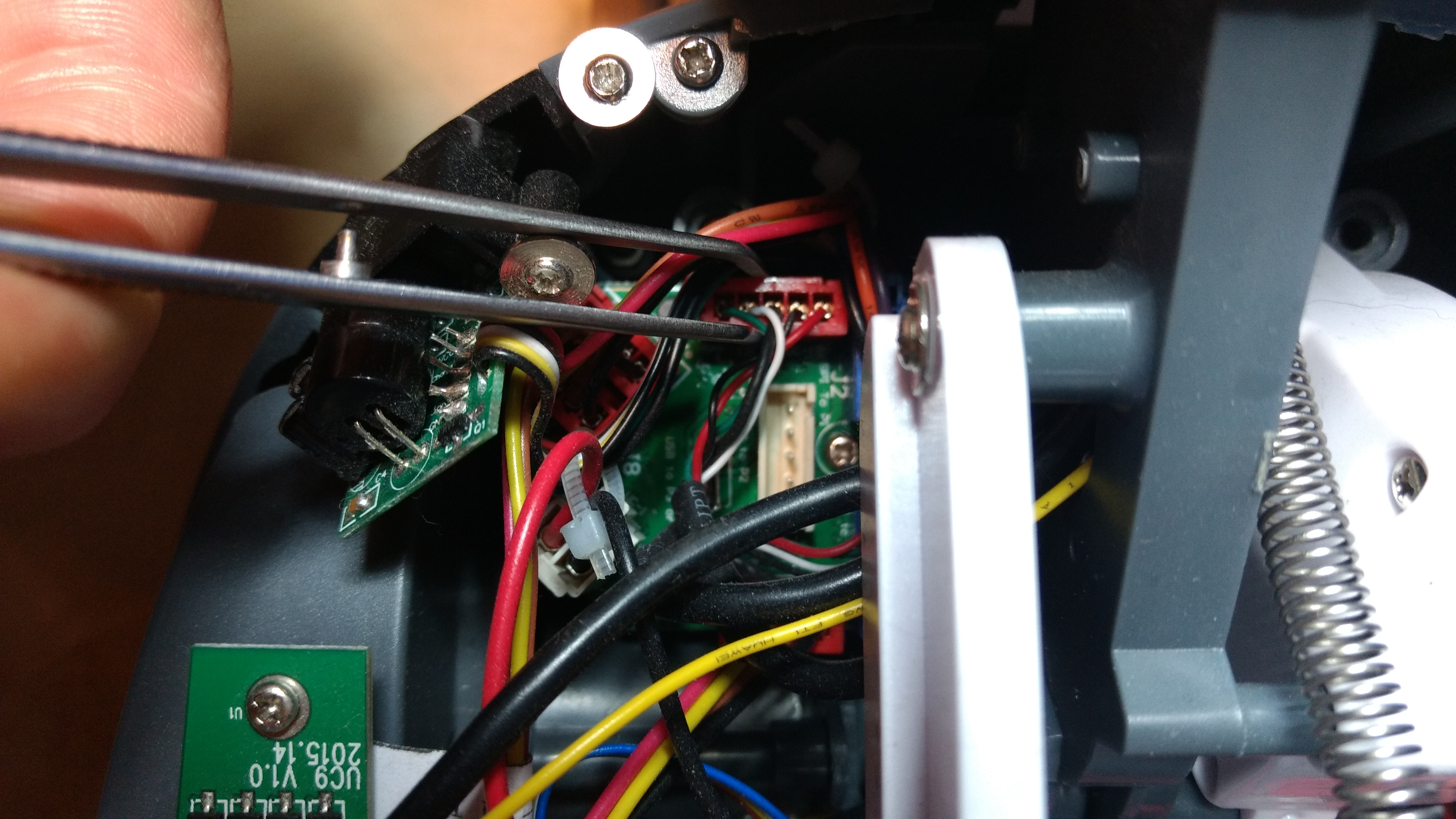
The port at C1:J4 links in the head. It is tricky to access—a good pair of tweezers is essential—but if disconnecting this clears the fault, the fault is in the head, and you should continue below under "Head". If the fault is present with this connector unplugged, the fault is—conversely—in the body, and you should continue round to the left hand side.
Head
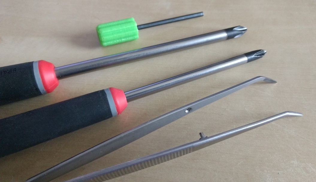
If you have isolated the fault to inside MIRO's head, you are encouraged to return your MIRO for further diagnostics, since opening (and re-closing) the head can be a hairy operation. However, if you are feeling brave—or in a hurry—you can use the head opening tool supplied with your MIRO (pictured right) to open up the head and continue the diagnostic in the same way.
Left hand side
Continue the diagnostic on the left hand side of MIRO, where there are only two boards, UC1 and UC9, both of which connect directly to C1 (UC6 was already disconnected, above).
Processor board fault
If one of the processor boards is misbehaving, you may not be able to start demo mode or run the GUI, so some other approach may be needed. Below we list some clues you will need to help you find what's wrong.
| Preparation | Observation | Implication |
|---|---|---|
| Mode 0. | (1) LEDs are pulsing red, green, blue in sequence and nothing else is happening. | P1 cannot reach the P2 board; P1 is running fine, but P2 is either missing, failed, or misconnected. |
| Mode 0, unplug either blue plug from C1 board. | LEDs are pulsing red, green, blue in sequence and nothing else is happening. | P1 is operating correctly (we've disconnected it from P2 deliberately, just to check this). |
| (2) LEDs on P2 board (UC7) in head are flashing alternately red, green, red, green. | P2 is running just fine. | |
| Symptom (1) and (2) together. | P1 and P2 are not connected to one another—suspect the blue cable. | |
| LED0 on P3 board (UC13) is flashing at 1Hz. | P3 is running just fine; if LED1 is lit, it is also connected to the network, which means the wifi, antenna, and network credentials are all good. | |
| Red LED on Bluetooth board is lit. | Bluetooth module is powered and should be discoverable by pressing SCAN in MIROapp. | |
| Mode 12. | LEDs are pulsing white at turn-on. | P1 and P2 are both operating correctly, and can talk to each other fine. |
| LED0 on P3 board is flashing a "heartbeat" pattern (flicker, flicker, pause). | P3 is booting—if this continues indefinitely, boot has failed, and you should listen to the Debug Port to learn more or try reflashing the SD card to Reprogram P3. | |
| LED0 on P3 board is not flashing. | The monitor daemon on P3 has crashed, been stopped, or never started—Login to MIRO or listen to the Debug Port to see what's what (logs are at /tmp/log). |